USB Program Card for AGFrc Servos

Contact UsCustomer Reviews

USB Program Card for AGFrc Servos

Our Price:

$19.99


Quantity (5)

Availability 5 in stock
Weight 0.10 lbs
SKU AGF-SPV2
Manufacturer AGFRC Servos

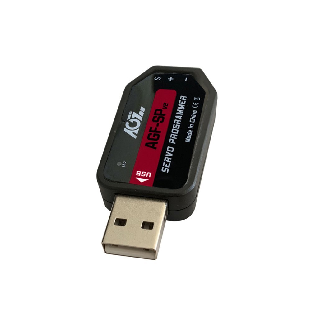
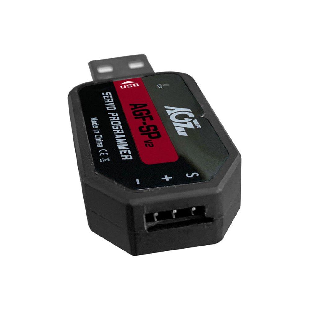
AGFrc AGF-SPV2 USB Program Card for AGFrc Servos with ASS marking

This card is the "Plug and Play" type USB programming card. It is easy to use and program the AGFrc programmable servos. Please note that this USB program card can only be used for AGFrc servos with ASS marking.

If you have questions for which AGFrc servo can be programmed, pls contact us for details. 

Software download from here: https://www.agfrc.com/index.php?id=download-center 

System Requirements:

  • Operating Voltage: USB(5V/500mA).
  • Operating System: Windows XP/Windows Vista/Windows 7/Windows 8 /windows10 ( 32/64bit).
  • Application: AGFrc Servos with ASS marking.

Software Menu Instructions:

1-1

The centre part is for information display window, while connect/ disconnect program card, or write/ Read servo parameter, it will show information. 


Parameter Function Instructions:

  • Servo Angle: Set the servo rotation angle
  • Servo Neutral: Set the servo neutral position Note: While the transmitter turn to the neutral position, if the servo do not stay in the corresponding position, it can modify this value to adjust the servo horn. This is equivalent to the trimming of transmitter channel. 
  • PWM Power: Adjust the servo output power. The higher the power, the higher the servo torque, current consumption will be high as well.
  • Damping Factor: Set the servo damping
  • Sensitivity: Adjust the servo dead band (sensitivity)
  • Soft Start: Slowly restoration while power on the servo. Once power on, the servo will gently turn to the position of current input signal.   Note: This function is to prevent damage from servo incorrect mounting while power on.
  • Inversion: Set normal and reverse rotation of the servo
  • Narrow Band: FUTABA SR Mode
  • SANWA SSR: SANWA SSR Mode   Note: Enable this function, it can support SANWA SSR high speed mode. Servo angle may be not accurate, it need to re-adjust.
  • Lost PPM Protect: Signal loss protection, there are three functions for selection,
    • a. Release: Non-Protection
    • b. Keep Position: Stay in the position before the signal loss
    • c. Go Neutral Position: Back to Neutral position (1500uS position)
  • Over Load Protect: Set the servo blocking protection, there are three levels, ticked to enable protection.
    •    Level 1: Set the starting time and power value of the primary protection.
    •    Level 2: Set the starting time and power value of the secondary protection.
    •    Level 3: Set the starting time and power value of the tertiary protection.
    •    Note: Left side is to set the protection starting time, right side is to set output power value after
  • Enable starting protection.
  • Servo Information: Servo information. Including servo model, version date, firmware name.
    •    Servo Name: Servo model
    •    Manufacture: Servo version date
    •    Firmware: Servo firmware name
  • Read: Read the servo parameter from the software interface.
  • Write: Write current parameter into servo.
  • Open: Open servo parameter file which saved on the computer.
  • Save: Save current servo parameter to the computer
  • UPF: Servo firmware upgrade function.
  • Exit: Exit and close the configuration software

Usage Instructions:

  1.  Plug in USB program card, this program card is free driver installation, wait for system auto install driver( around 5-10 seconds). While the hint as below pic appear at the bottom right corner, that means driver completed automatic installation. 

    1-2

  2. Open the software, it will show program card plug-in successfully in the information window. Otherwise it need to pull out the program card and re-plug again.

    1-3

  3. Plug in servo, click “Read” button to read servo parameter to current interface (as below pic),

    Note: Every time plug in servo, please "Read" the servo parameter first, then go ahead for modify

    the parameters to prevent servo dysfunction from improper operation.


     1-4 


Servo Firmware Update Instructions

1. While connected with the servo, click "UPF", select the upgrade firmware from the pop-up window, and click to upgrade(as below pic)

    1-5


2. During upgrading, information window will hint upgrade process, it will shows "Success Update" once completed(as below pic).

   1-6   


3. After finished updated the servo firmware, please click to “Read” the parameter first on the software interface.


: *
: *
: *
 

12V Smart Servo, USB Programmable, Waterproof, Mega Torque 60KG (834Oz)

12V Smart Servo, USB Programmable, Waterproof, Mega Torque 60KG (834Oz)

AGF-SA86BVMW

$145.99

Lemon RX DSMP (DSMX/DSM2 COMPATIBLE) MICROBRICK WITH 2 ON-BOARD SERVOS and 2.54MM HEADER PINS

Lemon RX DSMP (DSMX/DSM2 COMPATIBLE) MICROBRICK WITH 2.54MM HEADER PINS


Description:

Lemon Rx DSMX Compatible 6-Channel Receiver + Lemon DSMX Compatible Satellite


Type: DSMX Compatible Full Range Receiver
Number of Channel: 6
Modulation: DSMX Compatible (Also DSM2 backward Compatible)
Band: 2.4 GHz
Dimension: 25(L) x 18(W) x 11(H)  mm
Weight: 4.5 grams + 2.5 grams
Voltage Range: 3.45 - 8.4 V


Highlight
- FailSafe for all channels via press of a button
- DSMX Satellite port


Understanding the receiver


Setup Instruction

Binding

  1. Plug bind plug to the receiver.
  2. Provide power to the unit. LED flashes quickly.
  3. Enable bind mode in transmitter and ensure distance separation of 2 meters from receiver. Solid LED light means binding is completed.
  4. Remove bind plug.

Setting Failsafe

  1. Start by binding the receiver to the transmitter in the normal way and proceed as follows to set failsafe
  2. Ensure that transmitter and receiver are turned on.
  3. Insert bind plug into the receiver (Note: to set failsafe, bind plug is applied only when the receiver is turned on).
  4. Set transmitter controls to the desired failsafe positions.
  5. Press the side pushbutton to memorize failsafe settings.
  6. Observe that the green light at the end of the receiver turns on to indicate failsafe is set. (Repeat step 4 will cause the LED to turn off which means failsafe is disabled).
  7. Remove bind plug.
  8. Disconnect the power for at least 2 seconds and then reconnect the power again. Test failsafe by turning off the transmitter.


LM-0070H

$48.00

Hitec RDX2 Pro High Power 260W Dual Port AC/DC Charger

The X4-Eighty Multi-Charger features four identical and independent 80-watt power outputs for a total output of 320 Watts. Each microprocessor-controlled port is capable of charging all types of rechargeable batteries at up to 6 amps. Four individual balancing ports eliminate the need for a separate balancer when charging Lithium batteries. Equipped with a twin fan cooling system and an internal sensor for controlling fan speed, the X4-Eighty delivers the reliability and safety required to charge your LiPo, LiFe, Li-Ion, NiCd, NiMh or Lead Acid batteries. Its powerful capability combined with its reliable, safety functions make it the perfect choice for all electric and nitro modelers. Whether you are a weekend flier, an aerobatic master, a heli pilot or a mid-level to pro basher or racer, this is the charger for you.


Stock# 44169: Hitec X4-Eighty Four-Channel Multi-Charger

Download the Manual HERE

Input Requirements: 12 - 15 Volts DC, 30 Amp Minimum

Charging Specifications

Battery Type

Number of Cells

Voltage Level

Max. Charge Voltage

Max. Fast Charge Rate

Min. Discharge Voltage

NiCd

1 - 15

1.2V / Cell

1.5V / Cell

1 - 2C*

0.85V / Cell

NiMh

1 - 15

1.2V / Cell

1.5V / Cell

1 - 2C*

1.0V / Cell

Li-Ion

1 – 6

3.6 / Cell

4.1V / Cell

1C

2.5V / Cell

LiPo

1 – 6

3.7V / Cell

4.2V / Cell

1C

3.0V / Cell

LiFe

1 – 6

3.3V / Cell

3.6V / Cell

4C

2.0V / Cell

Pb (Lead Acid)

1 - 10

2.0V / Cell

2.46V / Cell

0.4C

1.75V / Cell

SPECIAL FEATURES

Optimized Operating Software
The software in X4 Eighty automatically controls the current rate during the charging or discharging process. This feature can prevent the user from overcharging their batteries which could lead to damage or injury. If the charger detects a malfunction, the circuit automatically disconnects and an alarm will sound, The operating functions of the X4 Eighty are controlled through a two-way communication link in order to maintain maximum safety with minimal errors. All of these functions and settings are easily configured by the user.

Internal Independent Lithium Battery Balancers
Each channel of the X4 Eighty employs an individual-cell voltage balancer eliminating the need for an external balancer for balance charging.

Charges Most Popular Lithium Batteries
The X4 Eighty is compatible with the three most common Lithium chemistry batteries, Li-Ion, LiPo and LiFe

Multiple Lithium Battery Charge Modes
The X4 Eighty's programming allows for Fast Charge, Balance Charge or Storage Charge Modes for LiPo, Li-Ion, and LiFe batteries.

  • Fast Charge Mode: Reduces charging time, but does not balance the cells, this mode only charges the battery to approximately 90% capacity.
  • Balance Charge Mode: Monitors individual cell voltage, keeping the cells within an acceptable voltage range and charges the pack to peak capacity.
  • Storage Charge Mode: Used for long-term battery storage. Adjusts the voltage level so the battery will not be damaged during long term storage.

Delta Peak Technology for Maximum Safety
The automatic charge termination program utilizes Delta-Peak voltage detection. When the battery's voltage exceeds the threshold, the charge process is terminated automatically.

Automatic Charging Current Limit
The maximum charge rate can be manually set when charging NiCd or NiMH batteries. The X4 Eighty will auto-detect when the batteries are fully charged and shut off, even with low impedance NiMH packs.

Capacity and Processing Time Limit
The charging capacity is calculated as the charging current multiplied by time. If the charging capacity exceeds the maximum limit set by the user, the process will terminate automatically. Additionally the user can set the maximum amount of charging time. If the charging time exceeds this limit, the process will terminate automatically.

Temperature Threshold
The battery's internal chemical reaction causes the temperature of the battery to rise during the charging process. If the temperature exceeds the limit, the charging process will automatically terminate.
* This function is available by connecting an optional temperature probe, which is not included in our package.

5 User Customizable Presets Per Channel
The X4 Eighty features 5 individually customizable presets so the user can store the charge and discharge parameters for any particular battery type. These presets can be recalled for the desired battery type without the need for any additional programming.

Cyclic Charging / Discharging
Batteries can be set to automatically Charge/Discharge or Discharge/Charge up to a maximum of 5 cycles.

PC Based Analysis Using USB Communication*
The Hitec X4 Eighty offers a PC-based program which can analyze the characteristics of the battery via a USB port. It shows a graph of voltage, current and capacity curves. It also displays the individual voltage of each cell in the lithium battery pack.


* A PC-LINK USB adapter can be purchased separately.


HRC44301

$149.99

Punisher 4S Monster Truck RTR Version, (Blue, Red or Green)

Punisher 4S Monster Truck RTR Version, Blue

COR00292

$419.99